Tuesday, 28 May 2013

Building a sliding mount for my in car radio - Part 4


Now that I have my car back after its accident, I was able to attach the fixed plate that makes up the mounting point for my slide mount. I may trim the screws so that they fit flush but they don’t get in the way at the moment. The plate fits well giving a sturdy base to slide the radio onto. When the radio is in position it is very accessible and doesn’t interfere with my driving position or getting in and out of the car. The next  job is to run the power lead from the battery through the bulkhead. The end of the lead will then be stored in the dropdown tray behind the radio. I will then do something similar with the antenna lead so that it is always available at the radio end and easy for me to connect the lead from the mag-mount at the other.

Top of the bracket fitted to the car. I’ll remove it and give it a coat of matt black paint so that it blends in better.
 
 
The radio slid into position.


Thursday, 2 May 2013

Building a sliding mount for my in car radio - Part 3


I have now soldered the two channels onto the brass base. I held the channels in place with some bent paperclips which actually did a very good job. I cleaned the brass and applied some flux before heating it. The solder ran smoothly between the parts and made good clean joints. The top part of the mount slides smoothly in the channels and should hold the radio securely to the underside of my dashboard. The next job is to clean up the brass and remove any flux and excess solder.

Paperclips did a good job of holding the parts
 
 
All the parts soldered in place
 

 The finished parts showing the top mount slid into place

Tuesday, 30 April 2013

Building a sliding mount for my in car radio - Part 2


The main part of the bracket has now been drilled and the holes countersunk. I cut down four screws and will be using both flat and crinkle washers. The preformed channels have had one end folded over and silver soldered. The next job is to clean up the brass and position the first channel ready for soldering. I plan to hold the channel in place with some bent paper clips. Hopefully this will do the job without the parts moving about. Once the first one has been soldered in position I’ll arrange the second channel so that the top part of the bracket slides in without binding. After both have been soldered I’ll have the fun of cleaning it all up.

Thursday, 25 April 2013

Building a sliding mount for my in car radio


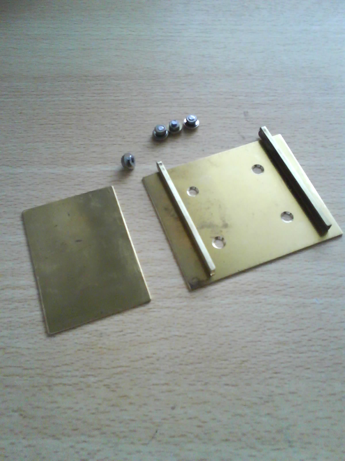
Now that the weather is getting better, I am looking to fit my mobile radio into my car. I don’t want it to be a permanent fixture as it could be stolen if left in unattended. I have decided on where I want to fit the radio and have devised a bracket design that will allow me to slid the radio in and out. I’ll still have to connect the power and antenna but this will only take a few seconds. I am going to make the brackets out of various pieces of brass soldered together. I have cut out the bits I’ll need and a photograph of these is shown below. My next job is to fabricate the channels so that they are blocked at one end. These will then be soldered onto the larger sheet of brass which I’ll attach to the radio mount. The small sheet of brass will be mounted in the car where the radio bracket will slid over it. When I get some spare time to do the drilling and soldering I’ll post the next set of pictures.

Monday, 4 February 2013

Video of my shortwave radio Christmas present


Here is a short video clip that shows the shortwave radio kit that I built over Christmas. I tried both my vertical and horizontal antennas and both appeared to give similar results. Whilst tuning around the bands (12MHz to 18MHz) I received several foreign stations. Near the end of the video is a short audio clip. Rather annoyingly I was also picking-up some local interference. The signals appeared to be fading so were coming in via the sky wave, which is probably why my different polarized antennas gave a similar signal strength. I will try the radio under different weather conditions and different times of the day to see if the results change. There are several beacons within the receivers range so this would be a handy way of checking propagation.
 

Thursday, 17 January 2013

Yaesu FT-1900


As a diehard Yaesu fan, I couldn’t resist getting one of their mobile transceivers for the car.  Now to spend a few days programming in all the local repeater offsets. With any luck I'll post some more details of this rig in the next few weeks.


Monday, 7 January 2013

Maxitronix short wave radio kit


At work this year I was given a Maxitronix short wave radio from my “secret Santa”. This is an interesting kit designed for anyone over the age of eight. I have my doubts that such a youngster could construct this without the help of an adult. The kit has part number MX-901SW and covers the frequencies from 6 to 8 MHz and 12 to 18 MHz. The kit has been designed so that no soldering is required. The wires from the various components link together by trapping them between spring like connectors. Whereas most of the components are individual items, there is a constructed circuit board that has several wires to connect up. The two coils are pre wound which is useful but I was a little disappointed as I rather like winding these. The instruction manual is well written and the steps are easy to follow. Here are some images of the parts in the box.


The first task is to “screw” the springs into the cardboard board. This board has the circuit diagram printed on one side which makes it easy to see where everything goes. The instructions recommend that you use a pencil placed on the end of the spring to help twist / push the item so that half is exposed either side of the board. This seems to be easy until you try it. The springs refuse to position themselves correctly and tend to distort or unwind. At one point I managed to cut myself on one of these and liberally covered the underside of the board in my blood. It is for this reason that I doubt that an eight year old would have fared any better. My solution to this problem is to first enlarge the holes on the board by inserting the pencil and wiggling it about to increase the size. The springs will then screw into the holes as described with little effort. On the side of the board that is not printed, it is recommended that you write the corresponding number next to the spring. This makes it easier to get the wiring correct first time. Here are some images of the underside of the board with the numbers added and the top side of the board once all the springs have been connected.


The next job is to insert the components in stages as described in the instructions. It is a simple case of bending the leads with a pair of pliers, pushing them through the holes in the board and bending over the legs. By pushing the spring to one side the coils open up and the leg of the component can be slid in and trapped. Some of the springs take several leads so best to place the first ones as low as possible to leave room for the others. It doesn’t take long to fit these but care needs to be taken when fitting some capacitors and the battery leads that they are wired round the right way. One of the coils is fitted to a ferrite rod and the other sits next to it. The wire from these coils is a little long and could easily be trimmed. If you do this, you must remember to remove some of the insulation before trapping the leads in the springs. The pre-constructed circuit board is screwed to the board and its wires easily connected.


 The battery and tuning capacitor are fixed to the plastic chassis that holds the board. I would then recommend that you double check the wiring to ensure everything is connected correctly and the right way round. The transistor has short legs so ensure this is fitted as instructed and all legs securely clamped. Once you are happy with your work, you need to decide which frequency range you want to listen to and connect to correct flying leads. Unravel the antenna and connect the battery and earpiece. Here is an image of the completed radio.


 I was able to construct this in about an hour. Because I was running out of time I wasn’t able to give the radio a full test. I can confirm that the volume was good and when tuning across the bands I was able to pick up some Morse. In the second part of this blog post I will connect the radio to my external antenna and see how it gets on with receiving some beacons around the country. 

If you have any questions about this kit or are having problems with yours, please contact me and I’ll try to help.
 
A copy of the manual in PDF format can be viewed here: http://www.elenco.com/admin_data/pdffiles/MX901SW.pdf