With Christmas over and the cold weather preventing me doing much outside, I’m back working on my homebrew transceiver project. With so many sections requiring power, I’ve added a central power point from an upturned strip of Veroboard. I have just added a microphone amplifier circuit. I plan to feed that from a constant signal source so I can check the gain and response over the 300Hz to 3KHz audio range.
This blog covers amateur radio advice and techniques. I plan to show the reader how to get started in ham radio after they have passed the exams. A lot of the news will be based on homebrew projects. Please leave comments if you would like more details on any of the subjects I talk about.
Sunday, 9 January 2022
Sunday, 12 December 2021
Building a HF SSB Transmitter
Just over a year ago I started building a HF transmitter. This started well but I soon realised that my old oscilloscope wasn't up to the task, so I splashed out the cash on a new one. Shown below are a series of pictures showing the progress. I stopped in the spring as I had many other jobs to do but now that winter is here, I'll be working on the transmitter again.
Friday, 18 July 2014
Building a DC to 2.5GHz stepped attenuator
Whilst sorting out some of my late fathers electronics, I came across an attenuator he was planning to build. Unfortunately his illness didn't allow him to start the project let alone finish it. In his memory I have built the attenuator and hope that he would have been pleased with the finished item.
The unit is based around a Weinschel 3007-100 stepped attenuator. It can apply 0 to 10dB of attenuation with an accuracy of plus or minus 0.3dB. It will work from DC to 2.5GHz and handle an input of up to 1 Watt. It has a 50 ohm impedance and should give a SWR of 1.3:1. The connectors of this sturdy unit are SMA. I managed to find some suitable coax and a couple of BNC chassis sockets that would take this rather thin cable. A trip to Maplin provided a suitable box. As the attenuator is connected using coax it was possible to select a plastic box rather than having to drill and file holes in a cast metal one. The hardest part of the build was wiring the SMA connectors. The miniature coax proved problematic on the eyes and fiddly with the fingers. The first cable was a pain but the second one seemed to be going well (may be too well). A quick test with a multi-meter showed that it had a short in one of the plugs. Fortunately I hadn't cut the coax too short so was able to cut it and start again.
After spending a few minutes each day for four days, the attenuator is now finished and fitted neatly in its box. The final job is to print the details on to some paper which I'll laminate and stick to the lid of the box. I had fun making this and hope to try it out once I complete my next project, a digital VFO.
Here are some pictures of the attenuator. I had to change some of the parts my father had sourced as the coax I used wouldn't fit his connectors.
The unit is based around a Weinschel 3007-100 stepped attenuator. It can apply 0 to 10dB of attenuation with an accuracy of plus or minus 0.3dB. It will work from DC to 2.5GHz and handle an input of up to 1 Watt. It has a 50 ohm impedance and should give a SWR of 1.3:1. The connectors of this sturdy unit are SMA. I managed to find some suitable coax and a couple of BNC chassis sockets that would take this rather thin cable. A trip to Maplin provided a suitable box. As the attenuator is connected using coax it was possible to select a plastic box rather than having to drill and file holes in a cast metal one. The hardest part of the build was wiring the SMA connectors. The miniature coax proved problematic on the eyes and fiddly with the fingers. The first cable was a pain but the second one seemed to be going well (may be too well). A quick test with a multi-meter showed that it had a short in one of the plugs. Fortunately I hadn't cut the coax too short so was able to cut it and start again.
After spending a few minutes each day for four days, the attenuator is now finished and fitted neatly in its box. The final job is to print the details on to some paper which I'll laminate and stick to the lid of the box. I had fun making this and hope to try it out once I complete my next project, a digital VFO.
Here are some pictures of the attenuator. I had to change some of the parts my father had sourced as the coax I used wouldn't fit his connectors.
The parts
The first lead completed
The finished attenuator
Labels:
2.5GHz,
amateur radio,
attenuator,
DC,
ham radio,
Weinschel
Monday, 24 June 2013
Building an inverted “L” antenna
The other day, quite by accident, I realised that my end fed
HF wire antenna had some issues. For a while now I have noticed that the bands
appeared to be very quiet. Where once the PSK frequencies had been busy they
now appeared dead. It so happened that I was tuned in to the 20m band but
needed to change the antenna leads about. As I started to unscrew my HF antenna
the band burst into life. It appeared that when the shielded side of the PL259 plug
touched the rigs socket, the signal strength vanished. If I positioned the
connector so that just the centre of the plug was used, I could hear lots of
PSK signals. I experimented by connecting my 2m antenna to the HF socket on the
rig and I could still hear everything. I therefore concluded that my wire
antenna had developed a fault. I had been thinking about changing this antenna
for a few months now so here was the opportunity I needed.
I have decided to build an inverted “L” with the aim of
making it resonate at one frequency. Although I use a tuner, I’d like to get
maximum performance on at least one band. My initial approach was to get
something working with the view to cutting it to length at a later date.
I needed to drive in a copper earthing point so that was my
first job. I used a section of copper water pipe and hammered that into the
ground near to the antenna feed point. I didn’t want to damage the top of the
copper pipe so I used a jubilee clip to give some strength and support and then
fitted a wide headed bolt to the top of the tube. I rolled some paper around
the thread of the bolt so that it was a tight fit. This hammered into the
ground quite easily as this area of ground never gets the sun so is always
damp. I then connected the shield of the coax to the earth and the centre to my
antenna wire via a terminal block. The “L” shape of the wire has a slightly
longer horizontal length over the vertical length. For now this is fine until
the second stage which will be to tune the antenna. I plan to screw a box to
the wall which will consist of a copper back plate connected directly to my
earth rod. I will then attach some sockets to this to enable me to easily connect
my inverted “L” and any other experimental antennas. For now I have water
proofed the earth and antenna connection as shown in the picture below.
Back at the transmitter, I can once again hear the signals I
would expect to hear. At the moment the vertical part of the “L” is next to my
house which is far from ideal. If this antenna proves itself I will look to
feed it from the other end, reducing possible interference.
The earth rod prepared for being hit with a
hammer
Temporary connections made waterproof
A view skywards following the vertical path of the “L”
Tuesday, 18 June 2013
Building a sliding mount for my in car radio - Part 5
Just had lots of fun running the 12v supply from the engine bay
of my car to a point just under my dashboard. Modern cars really know how to
squeeze every last inch of space. After an hours hard work and some cut hands I
finally got the cable to the correct location. I was happy to see my rig
powering up and quickly grabbed a SWR meter to test the antenna. With an output
of 50 Watts I have a near 1:1 SWR across the repeater and main transmission
frequencies. A quick audio check confirmed I could contact Kent from the
Danbury repeater. My next test is to try out the rig whilst mobile, probably on
my way to work. The rig sits nicely on its slide mount and can be easily fitted
and removed. I’ll probably run a short length of coax so that when I fix the
mag mount I won’t have trailing leads in the foot well. Let me know if you plan
to make your own slide mount and need any advice.
Tuesday, 28 May 2013
Building a sliding mount for my in car radio - Part 4
Now that I have my car back after its accident, I was able
to attach the fixed plate that makes up the mounting point for my slide mount.
I may trim the screws so that they fit flush but they don’t get in the way at
the moment. The plate fits well giving a sturdy base to slide the radio onto.
When the radio is in position it is very accessible and doesn’t interfere with
my driving position or getting in and out of the car. The next job is to run the power lead from the battery
through the bulkhead. The end of the lead will then be stored in the dropdown
tray behind the radio. I will then do something similar with the antenna lead
so that it is always available at the radio end and easy for me to connect the
lead from the mag-mount at the other.
Top of the bracket fitted to the car. I’ll remove it and
give it a coat of matt black paint so that it blends in better.
The radio slid into position.
Thursday, 2 May 2013
Building a sliding mount for my in car radio - Part 3
I have now soldered the two channels onto the brass base. I
held the channels in place with some bent paperclips which actually did a very
good job. I cleaned the brass and applied some flux before heating it. The
solder ran smoothly between the parts and made good clean joints. The top part
of the mount slides smoothly in the channels and should hold the radio securely
to the underside of my dashboard. The next job is to clean up the brass and
remove any flux and excess solder.
Paperclips did a good job of holding the parts
All the parts soldered in place
The finished parts showing the top mount slid into place
Tuesday, 30 April 2013
Building a sliding mount for my in car radio - Part 2
The main part of the bracket has now been drilled and the
holes countersunk. I cut down four screws and will be using both flat and crinkle
washers. The preformed channels have had one end folded over and silver
soldered. The next job is to clean up the brass and position the first channel
ready for soldering. I plan to hold the channel in place with some bent paper
clips. Hopefully this will do the job without the parts moving about. Once the
first one has been soldered in position I’ll arrange the second channel so that
the top part of the bracket slides in without binding. After both have been
soldered I’ll have the fun of cleaning it all up.
Thursday, 25 April 2013
Building a sliding mount for my in car radio
Now that the weather is getting better, I am looking to fit
my mobile radio into my car. I don’t want it to be a permanent fixture as it could
be stolen if left in unattended. I have decided on where I want to fit the
radio and have devised a bracket design that will allow me to slid the radio in
and out. I’ll still have to connect the power and antenna but this will only
take a few seconds. I am going to make the brackets out of various pieces of
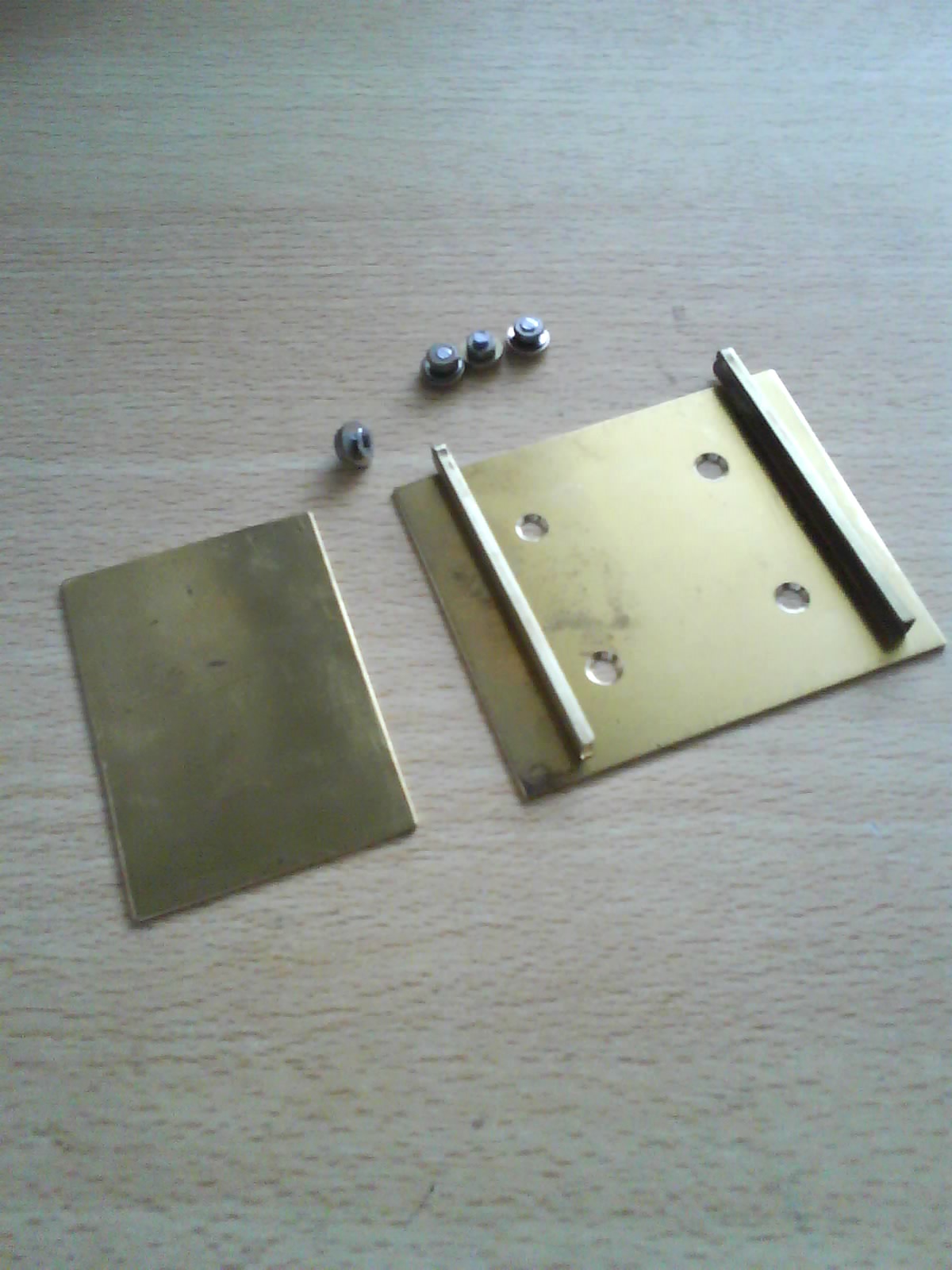
brass soldered together. I have cut out the bits I’ll need and a photograph of
these is shown below. My next job is to fabricate the channels so that they are
blocked at one end. These will then be soldered onto the larger sheet of brass
which I’ll attach to the radio mount. The small sheet of brass will be mounted
in the car where the radio bracket will slid over it. When I get some spare
time to do the drilling and soldering I’ll post the next set of pictures.
Monday, 4 February 2013
Video of my shortwave radio Christmas present
Here is a short video clip that shows the shortwave radio
kit that I built over Christmas. I tried both my vertical and horizontal
antennas and both appeared to give similar results. Whilst tuning around the
bands (12MHz to 18MHz) I received several foreign stations. Near the end of the
video is a short audio clip. Rather annoyingly I was also picking-up some local
interference. The signals appeared to be fading so were coming in via the sky
wave, which is probably why my different polarized antennas gave a similar signal
strength. I will try the radio under different weather conditions and different
times of the day to see if the results change. There are several beacons within
the receivers range so this would be a handy way of checking propagation.
Thursday, 17 January 2013
Yaesu FT-1900
As a diehard Yaesu fan, I couldn’t resist getting one of
their mobile transceivers for the car. Now
to spend a few days programming in all the local repeater offsets. With any luck I'll post some more details of this rig in the next few weeks.
Labels:
2m,
amateur radio,
FT1900,
mobile,
Radio,
transceiver,
Yaesu
Monday, 7 January 2013
Maxitronix short wave radio kit
At work this year I was given a Maxitronix short wave radio
from my “secret Santa”. This is an interesting kit designed for anyone over the
age of eight. I have my doubts that such a youngster could construct this
without the help of an adult. The kit has part number MX-901SW and covers the
frequencies from 6 to 8 MHz and 12 to 18 MHz. The kit has been designed so that
no soldering is required. The wires from the various components link together
by trapping them between spring like connectors. Whereas most of the components
are individual items, there is a constructed circuit board that has several
wires to connect up. The two coils are pre wound which is useful but I was a
little disappointed as I rather like winding these. The instruction manual is well
written and the steps are easy to follow. Here are some images of the parts in
the box.
The first task is to “screw” the springs into the cardboard
board. This board has the circuit diagram printed on one side which makes it
easy to see where everything goes. The instructions recommend that you use a
pencil placed on the end of the spring to help twist / push the item so that
half is exposed either side of the board. This seems to be easy until you try
it. The springs refuse to position themselves correctly and tend to distort or
unwind. At one point I managed to cut myself on one of these and liberally
covered the underside of the board in my blood. It is for this reason that I
doubt that an eight year old would have fared any better. My solution to this
problem is to first enlarge the holes on the board by inserting the pencil and wiggling
it about to increase the size. The springs will then screw into the holes as
described with little effort. On the side of the board that is not printed, it
is recommended that you write the corresponding number next to the spring. This
makes it easier to get the wiring correct first time. Here are some images of
the underside of the board with the numbers added and the top side of the board
once all the springs have been connected.
The next job is to insert the components in stages as
described in the instructions. It is a simple case of bending the leads with a
pair of pliers, pushing them through the holes in the board and bending over
the legs. By pushing the spring to one side the coils open up and the leg of
the component can be slid in and trapped. Some of the springs take several
leads so best to place the first ones as low as possible to leave room for the
others. It doesn’t take long to fit these but care needs to be taken when
fitting some capacitors and the battery leads that they are wired round the
right way. One of the coils is fitted to a ferrite rod and the other sits next
to it. The wire from these coils is a little long and could easily be trimmed.
If you do this, you must remember to remove some of the insulation before
trapping the leads in the springs. The pre-constructed circuit board is screwed
to the board and its wires easily connected.
The battery and tuning capacitor
are fixed to the plastic chassis that holds the board. I would then recommend
that you double check the wiring to ensure everything is connected correctly
and the right way round. The transistor has short legs so ensure this is fitted
as instructed and all legs securely clamped. Once you are happy with your work,
you need to decide which frequency range you want to listen to and connect to
correct flying leads. Unravel the antenna and connect the battery and earpiece. Here is an image of the completed radio.
I was able to
construct this in about an hour. Because I was running out of time I wasn’t
able to give the radio a full test. I can confirm that the volume was good and when
tuning across the bands I was able to pick up some Morse. In the second part of
this blog post I will connect the radio to my external antenna and see how it
gets on with receiving some beacons around the country.
If you have any questions about this kit or are having
problems with yours, please contact me and I’ll try to help.
A copy of the
manual in PDF format can be viewed here: http://www.elenco.com/admin_data/pdffiles/MX901SW.pdf
Wednesday, 26 September 2012
My new 2m Power Amplifier
Now that I am using my Wouxun handheld unit in my car, I feel that its 5 watt output is a little on the weak side. Recently I spotted a 2m amplifier on eBay and decided to try a few bids. The device was described as untested but the seller said the lights came on and there was a circuit diagram available on the Internet. I kept my fingers crossed as the minutes ticked away but I eventually won the amplified for just over £30. It soon arrived so I set about making up some new patch leads so I could test it.
This amplifier produces around 30 watts of output from 5 watts in. It also has an adjustable RX amplifier. The unit is made by "Tokyo Hy-Power" and the model number is HL-37Vsx. I first decided to power it up and ensure it didn't do anything strange such as smoke or draw too much current. In its idle state all seemed well. I then connected it to my rig and antenna so I could test the RX amplifier. I found a suitable signal which was a conversation on the local Cambridge repeater. As you will see from the short video below, moving the sliding potentiometer adjusted the signal strength. This RX amplifier can be left at a suitable level or turned off altogether. As I tend to use the Cambridge repeater when mobile, I will probably set this to a reasonable level as it'll be hidden away and not accessible whilst driving.
Next on the "todo" list was to check the SWR whilst transmitting 5 watts into a dummy load. I did this with the amplifier switch off and then switched on. With the unit off the SWR was about 1.3:1 and with it on it was just about 1:1.
The final test was to see if the amplifier was living up to its name and actually amplifying. My transmitter was configured to output 5 watts. With the amplifier turned off and my power meter set to 20 watt fsd, the meter showed an output of just over 3 watts of FM.
I then changed my meter to display 200 watts fsd and switched on the amplifier. The meter showed an output of 40 watts of FM.
The manufacture's specification says I can expect an output of around 20 to 35 watts with a maximum input of 5 watts. With my meter showing an output of 40 watts I am happy that this is probably about right, give or take a few watts. At this point my dummy load was getting rather warm so I completed my basic testing. The next test will be to try some on-air contacts to see that the audio isn't being distorted etc. I will then need to buy some additional coax to enable me to set this up in my car. So far this amplifier seems like a good purchase.
This amplifier produces around 30 watts of output from 5 watts in. It also has an adjustable RX amplifier. The unit is made by "Tokyo Hy-Power" and the model number is HL-37Vsx. I first decided to power it up and ensure it didn't do anything strange such as smoke or draw too much current. In its idle state all seemed well. I then connected it to my rig and antenna so I could test the RX amplifier. I found a suitable signal which was a conversation on the local Cambridge repeater. As you will see from the short video below, moving the sliding potentiometer adjusted the signal strength. This RX amplifier can be left at a suitable level or turned off altogether. As I tend to use the Cambridge repeater when mobile, I will probably set this to a reasonable level as it'll be hidden away and not accessible whilst driving.
Next on the "todo" list was to check the SWR whilst transmitting 5 watts into a dummy load. I did this with the amplifier switch off and then switched on. With the unit off the SWR was about 1.3:1 and with it on it was just about 1:1.
The final test was to see if the amplifier was living up to its name and actually amplifying. My transmitter was configured to output 5 watts. With the amplifier turned off and my power meter set to 20 watt fsd, the meter showed an output of just over 3 watts of FM.
I then changed my meter to display 200 watts fsd and switched on the amplifier. The meter showed an output of 40 watts of FM.
The manufacture's specification says I can expect an output of around 20 to 35 watts with a maximum input of 5 watts. With my meter showing an output of 40 watts I am happy that this is probably about right, give or take a few watts. At this point my dummy load was getting rather warm so I completed my basic testing. The next test will be to try some on-air contacts to see that the audio isn't being distorted etc. I will then need to buy some additional coax to enable me to set this up in my car. So far this amplifier seems like a good purchase.
Labels:
2m,
amplifier,
FM,
mobile,
power meter,
SWR,
Tokyo Hy-Power,
Wouxan
Monday, 3 September 2012
Building a new matching transformer
Having a recent antenna failure I decided to rebuild the
matching transformer that feeds my end fed wire. This design comes from the “Emergency
Amateur Radio Club” based in Honolulu (http://www.earchi.org).
This project creates a trifilar wound 9:1 UNUN (unbalanced to unbalanced)
toroid matching transformer. This will match the high input impedance of an end
fed wire into a range that most antenna tuners can handle. The designer says it
should handle 100 watts of power.
The key parts are:
- A small plastic box (something that can be made waterproof)
- A powdered iron toroid (EG T106-2)
- Three 20 inch pieces of 22 gauge solid insulated copper wire (in three different colours if possible)
- An RF panel mounted connector (BNC or S0-239)
- You will also need the relevant screws, nuts and solder tags etc, to fit the package together.
Next job was to wind the toroid. As I didn’t have access to
different coloured copper wire, I instead fitted coloured sleeves to the ends
of each cut length.
It is important to keep the wires in the correct order and
not cross them as they are wound. They should be appear in the following order
(left to right), Green, Black and Red. Wrap these round the toroid 9 times as
shown in the picture below. I found that the first few windings were a little
loose so I added a couple at the end and unwound the loose ones from the start.
That way I still had 9 turns but a much better spread and even tightness. After
winding, ensure that the wires on the last turn are in the correct order. If they
aren’t then they must have twisted at some point.
It is important to get the next sections correct else you
will have to start again with new wire. Holding the toroid as in the above
picture, solder the “Left Black” wire to the “Right Red” wire. I found the best
way was to first scrape off the insulating coating from both wires where they
would touch. Then twist both wires together with a single turn. This will pull
both together and make a sound mechanical joint. Solder the two wires and
remove the trailing ends.
Next you need twist the “Left Green” wire and “Right Black”
wire together. First clean off the insulation before twisting together. This
joint needs to be attached to the centre connection of the RF connector fitted
to the box. Before cutting off the excess wire. Place the toroid into the box
to see where the cut should be made.
The (Left Red) wire should be cleaned and soldered to the
connector on the box that the wire antenna will be connected. The remaining
(Right Green) wire should be cleaned and soldered to the outer ground
connection of the RF connector.
Now inspect the solder joints for any dry joints and ensure
the box is free of any solder splashes etc. I used a silicon grease spread
around the lip of the box and lid before screwing the two together. In the past
I have used a silicon sealant, the type used in the bathroom. If you use this
type and it has the vinegar type smell, keep this away from and metal as it
tends to promote corrosion.
In the next few days I
hope to get up the ladder and fit the unit to my mast. I will take additional
pictures and post these in the next week or so. Please ask any related question
and I’ll try to assist. Further details including a kit of parts are available
from the EARC website: http://www.earchi.org
Tuesday, 21 August 2012
Matching transformer failure
The other day I attempted to work PSK only to find that I
had a very high SWR. My antenna tuner was clicking away but after a few seconds
it was clear that something had failed. Up the ladder I went and fort off the accumulation
of spiders to retrieve my matching transformer. Once opened, it was clear that
there had been some heating and probably arcing. I have taken a picture and
indicated the problem area with a yellow arrow. Fortunately I have plenty of
spare wire so I’ll wind a new transformer. This will be a temporary measure as
I have plans to replace my end fed wire with something less likely to cause
interference.
Thursday, 26 July 2012
Going mobile
It has taken a while to finally get this far but at long
last I’ve put together my mobile setup. I checked the SWR between the antenna
mounted centrally on the roof of my car and my Wouxan handheld. It is very
close to 1:1 across the frequencies I plan to use so no extra adjustments were
required. I plan to build a proper mounting bracket so that I can more easily
access the controls of the transceiver. So far I’ve just been listening to see
what the reception is like on my journey to and from work. I seem to get a
reasonable signal on a couple of the repeaters and the one at Danbury seems to
pick-up my signal, even though I’m only pushing out 5 Watts. As long as the reception
is acceptable I may look into the possibility of making a 2m amplifier to boost
my output.
Here are some pictures of my current in-car configuration.
Monday, 18 June 2012
Sharmans NR-770H and mag mount
I have just purchased a Sharmans NR-770H dual band mobile
antenna and six inch mag mount. The build quality of these items appears to be
good with no obvious areas for concern. Not too sure when I’ll get some spare
time to set these up on my car but hopefully it won’t be too far away.
Tuesday, 29 May 2012
Digital interface working PSK31 on 17m
Here are some screen shots of my homebrew digital interface working. I am running the Ham Radio Deluxe Digital Master 780 software which provides lots of handy functions. The waterfall display and macro options are far better than similar software I have used. As you can see, I have configured the application to send CQ on the 17m band. On the waterfall you will see that I have chosen a low noise area of the band and well away from the strong signal which is left of centre.
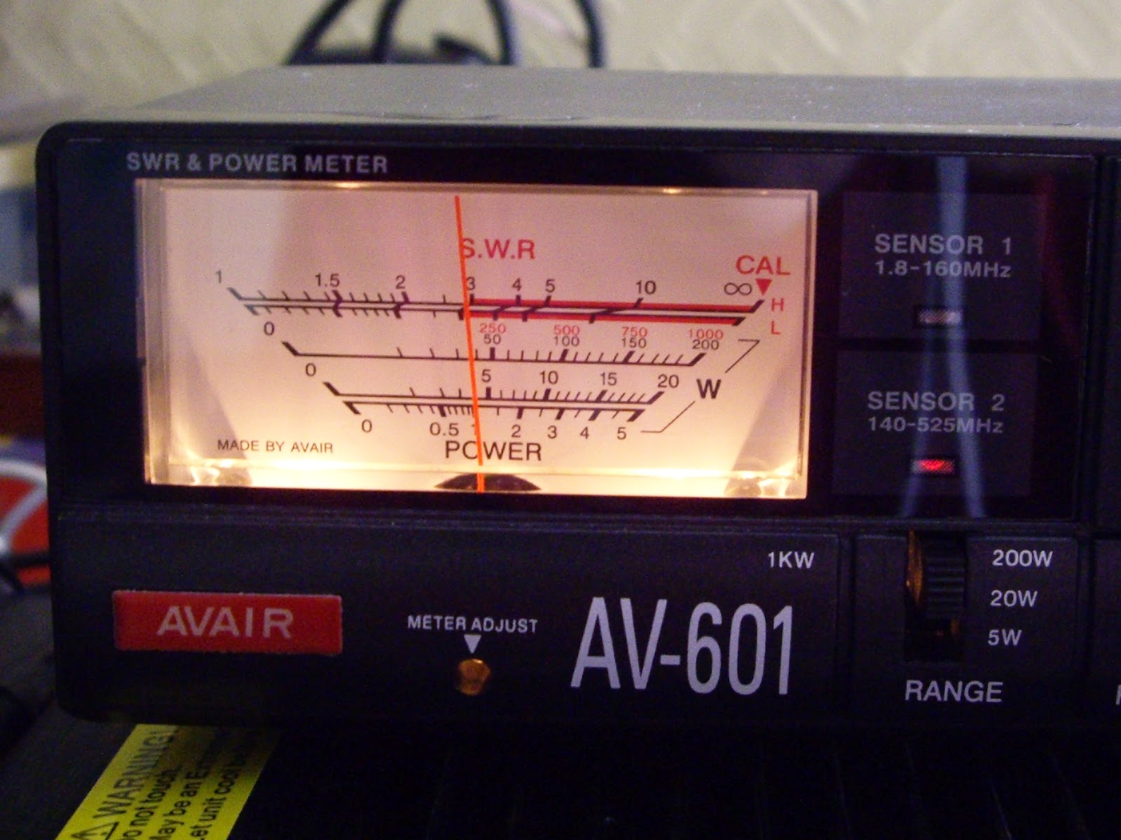
Here is my radio gear listening on the central frequency of the band. My digital interface has been labelled so I don’t need to remember the function of each knob. I recently added the Avair SWR/Power meter in-line to provide an analogue view of these values. The LDG antenna tuner also provides similar information but in a less granular digital way.
I have my rig configured so that the ACL is only just starting to activate. This is keeping the TX power output at around 20 to 30 Watts. Over driving the rig causes some interesting issues which I think are due to RF pick-up on the leads. I need to do some further testing with a dummy load and some ferrite cores to prove my theory. My HF antenna is an end-fed wire which isn’t ideal and could be causing some of my problems. For now I’ll keep the power low so that I don’t cause interference.
Subscribe to:
Posts (Atom)